Enhanced Light Crosswalk Illumination
Blue-spectrum lighting measurably improves nighttime pedestrian safety. Drivers detected pedestrians ~40 ft sooner than the existing baseline and ~26 ft sooner than 4000 K white, with faster reaction times.
UW–Milwaukee · UW–Madison · TAPCO
 Xiaowei (Tom) Shi, Ph.D.Principal InvestigatorAssistant Professor, UW–Milwaukee
tomshi@uwm.edu
 Xiao Qin, P.E., Ph.D.Co-PIProfessor, UW–Milwaukee
qinx@uwm.edu
 Xiaopeng Li, P.E., Ph.D.Co-PIProfessor, UW–Madison
xli2485@wisc.edu
 Brian Scharles Sr.Co-PIDirector of Product Innovation, TAPCO
brians@tapconet.com
 Muhammad FahadGraduate Research AssistantUW–Milwaukee
muhamm72@uwm.edu
Student team: Narayan Rai · Xiao Liang (UWM) · Bofeng Cao · Chengyuan Ma · Hangyu Li · Keke Long · Jiaxi Liu (UW–Madison) · Aleischa Kronshagen · Denise Lawien (TAPCO)
With sincere thanks to the WisDOT Project Oversight Committee and all participants.




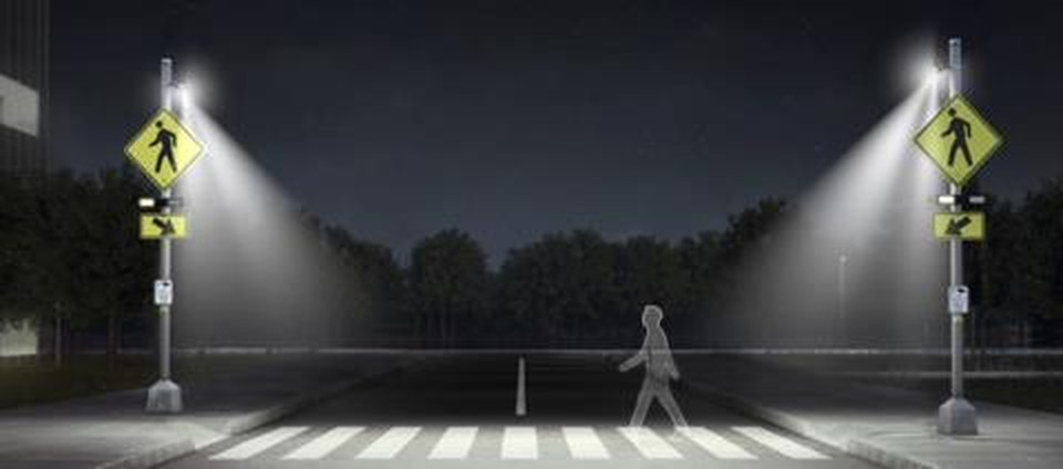
Improving pedestrian visibility at night
This project evaluates how enhanced crosswalk illumination influences driver detection and response at night. Using controlled field experiments, the team examines lighting spectrum, installation geometry, pedestrian characteristics, and roadside conditions.
SafeWalk™ prototype with seven adjustable spectra
Purpose-built LED crosswalk illuminator (TAPCO SafeWalk 2.0), configured for field research.
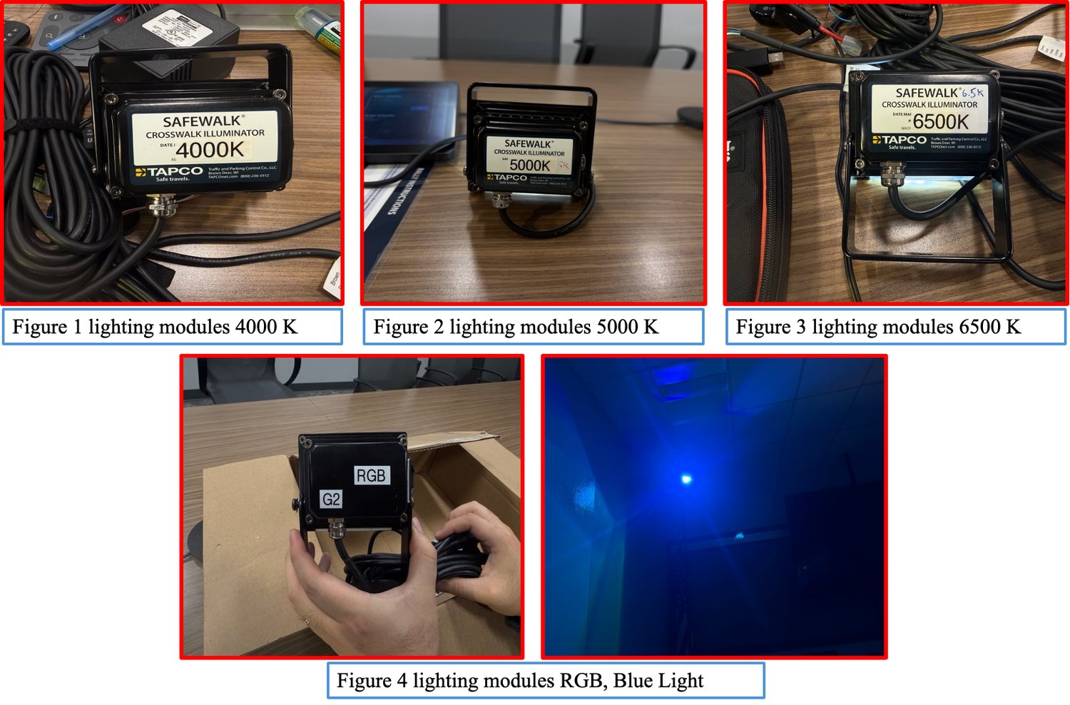
| Configuration | Type | Rationale |
|---|---|---|
| 4000 K | Neutral white | FHWA / agency reference |
| 5000 K | Cool white | One step above standard |
| 6500 K | Daylight white | Upper white-light boundary |
| Blue Baseline | Blue-shifted LED | Reference blue configuration |
| Ice Blue | Blue-shifted LED | Blue + white mix, highest luminance |
| Sky Blue | Blue-shifted LED | Mid-intensity mix |
| Pure Royal Blue | Saturated blue | Maximum blue saturation |
Seven spectral configurations: the agency-recommended white range plus the blue-shifted range never before field-tested in Wisconsin.
281 nighttime rounds at two Wisconsin sites
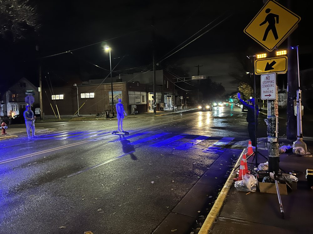
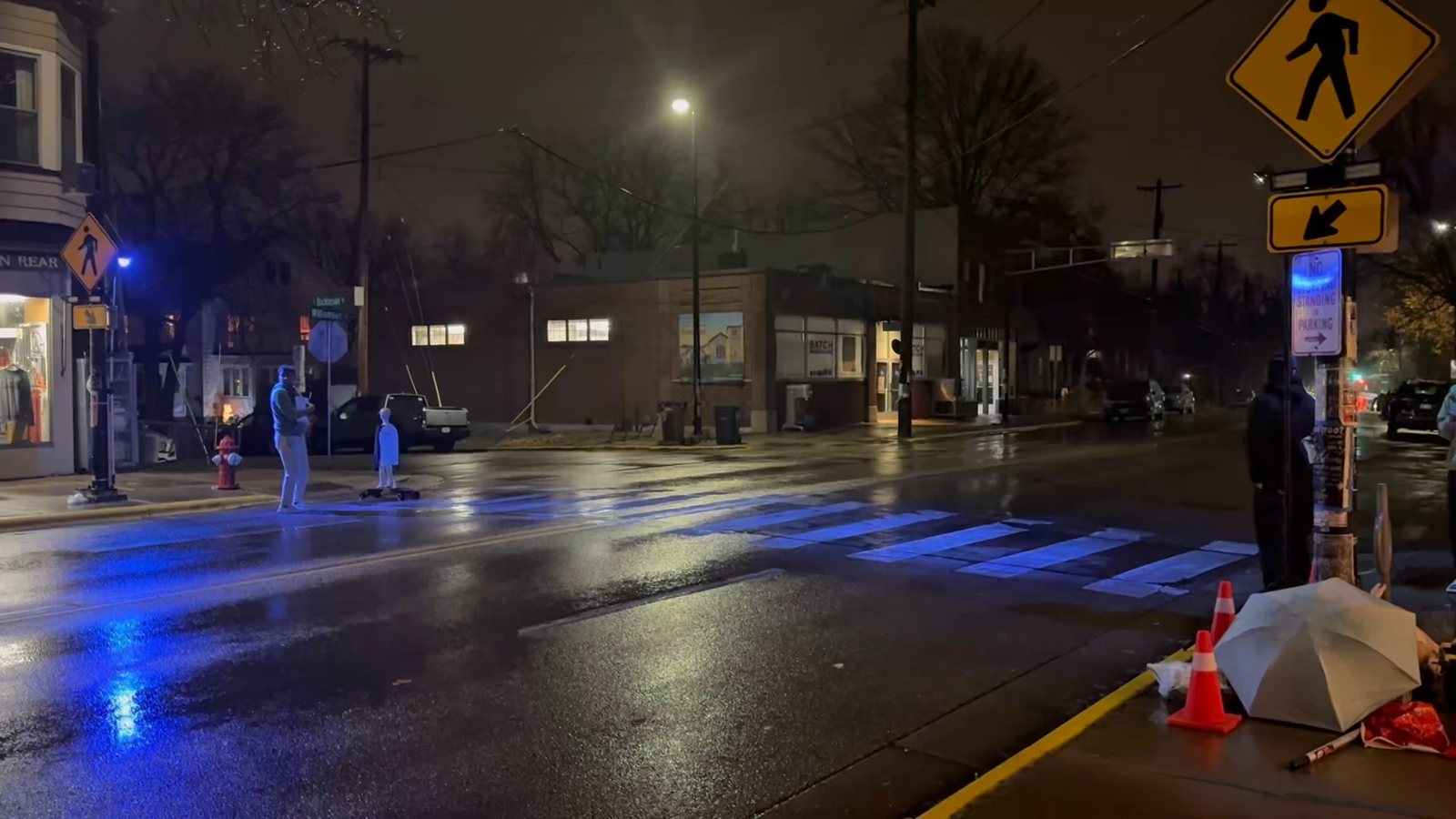
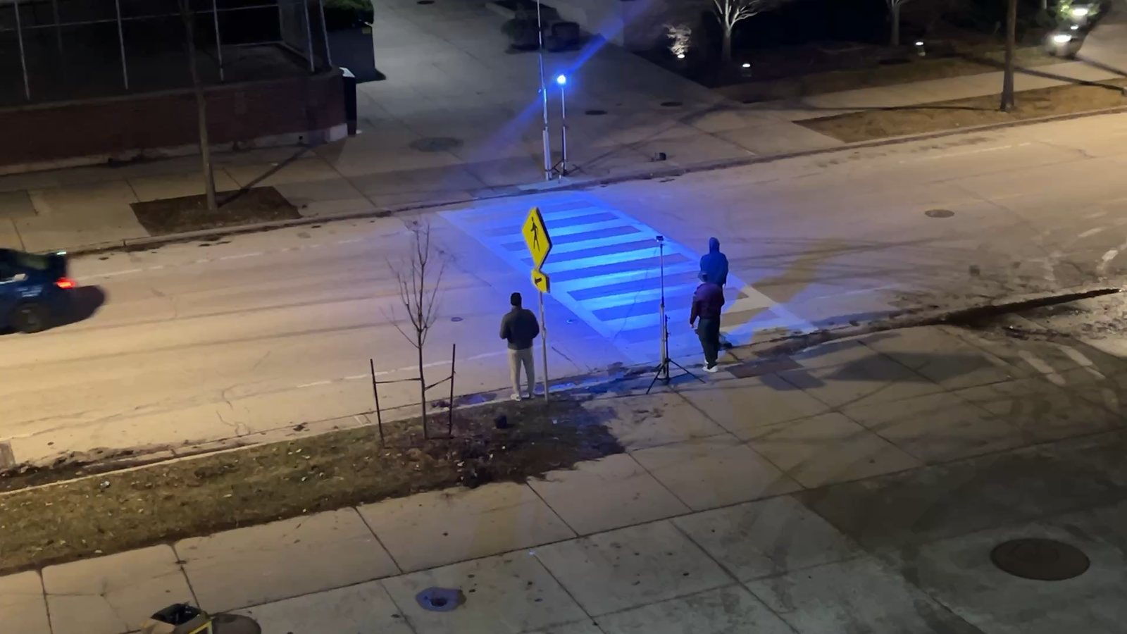
An instrumented probe vehicle approached the crosswalk while a mannequin on a remote-controlled electric skateboard crossed, creating repeatable pedestrian events on real roads, on real nights.
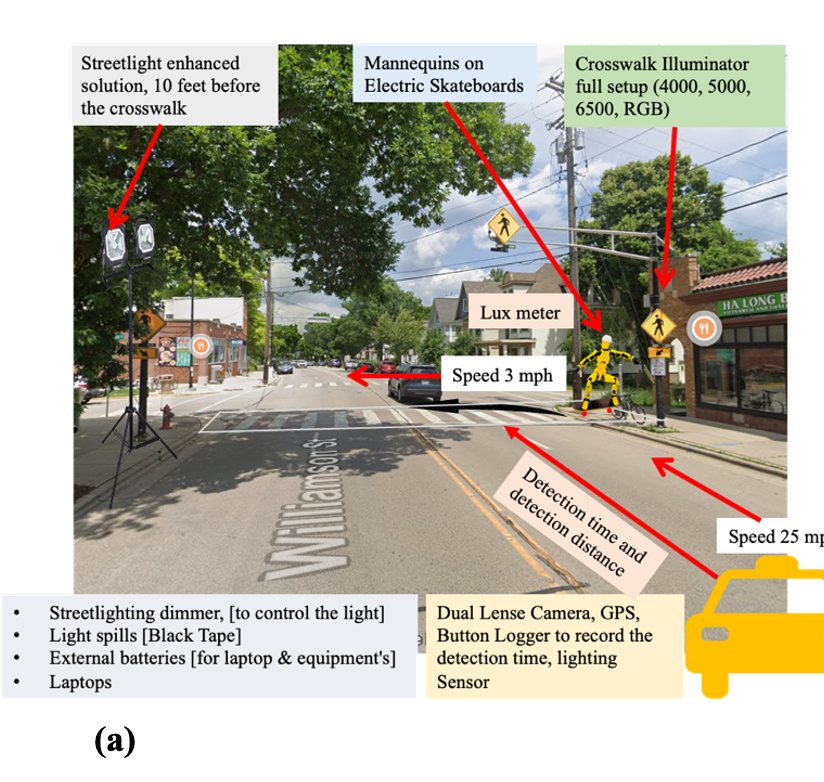
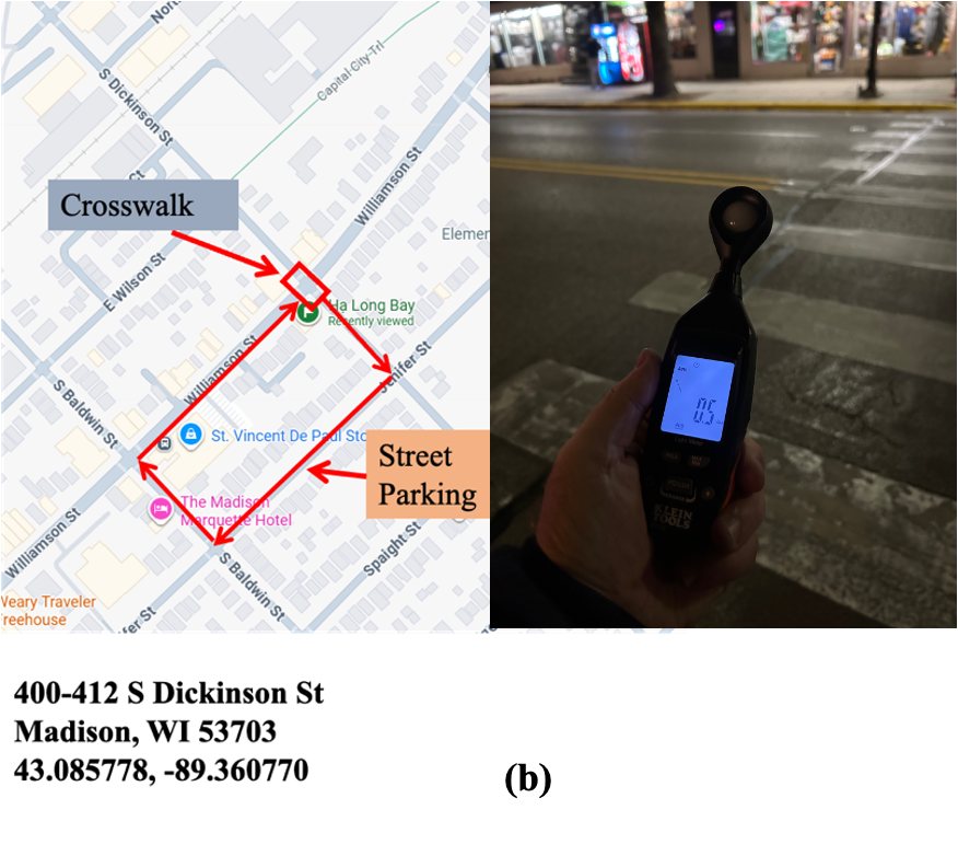
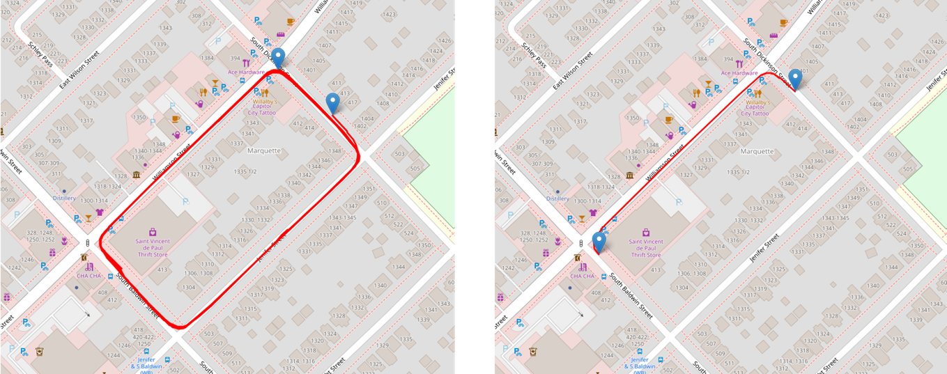
Williamson St & S Dickinson St
Wider 4-lane urban roadway · existing RRFB + push buttons · visually complex background.
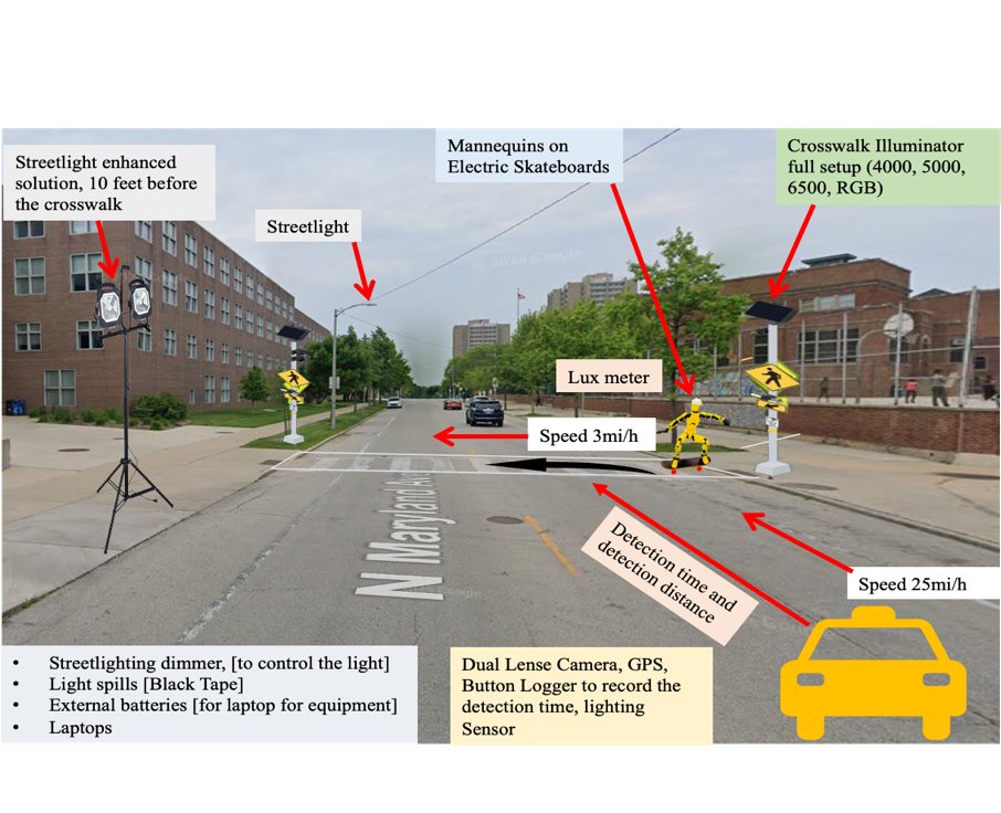
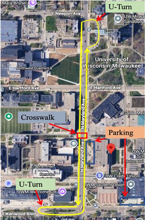
N Maryland Ave · UWM campus
Two-lane campus roadway · no RRFB or push button · ambient street lighting.
What we varied
| Factor | Levels |
|---|---|
| Lighting spectrum | 4000 K · 5000 K · 6500 K · 4 blue configs |
| Mounting height | 3 heights per site |
| Lateral distance | 0 / 9.5 / 16.5 ft (Milwaukee) |
| Pedestrian target | Adult & child mannequins |
| Clothing | Dark blue & white |
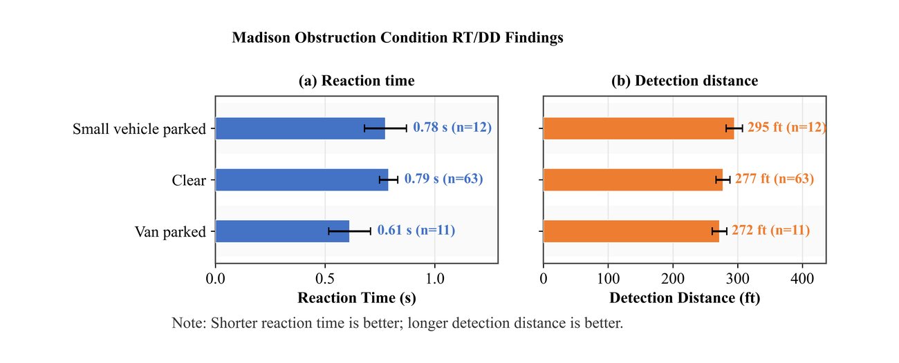
| Obstruction | Clear · small vehicle · van parked |
| Weather / ambient | Clear night · light rain · ± streetlight |
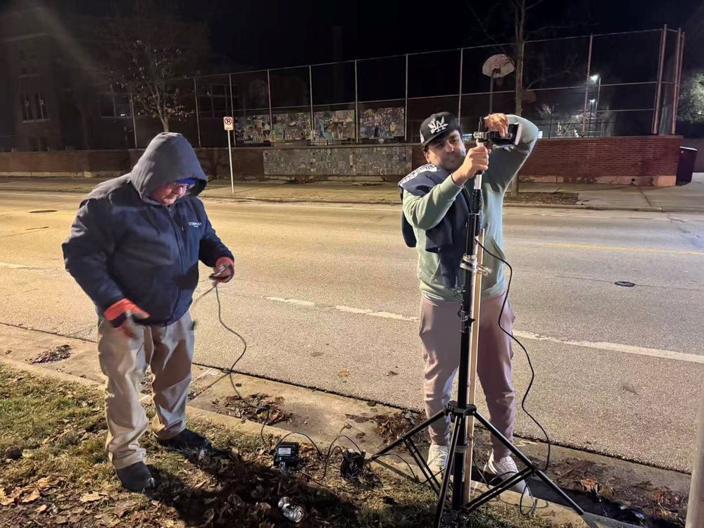
Instrumentation
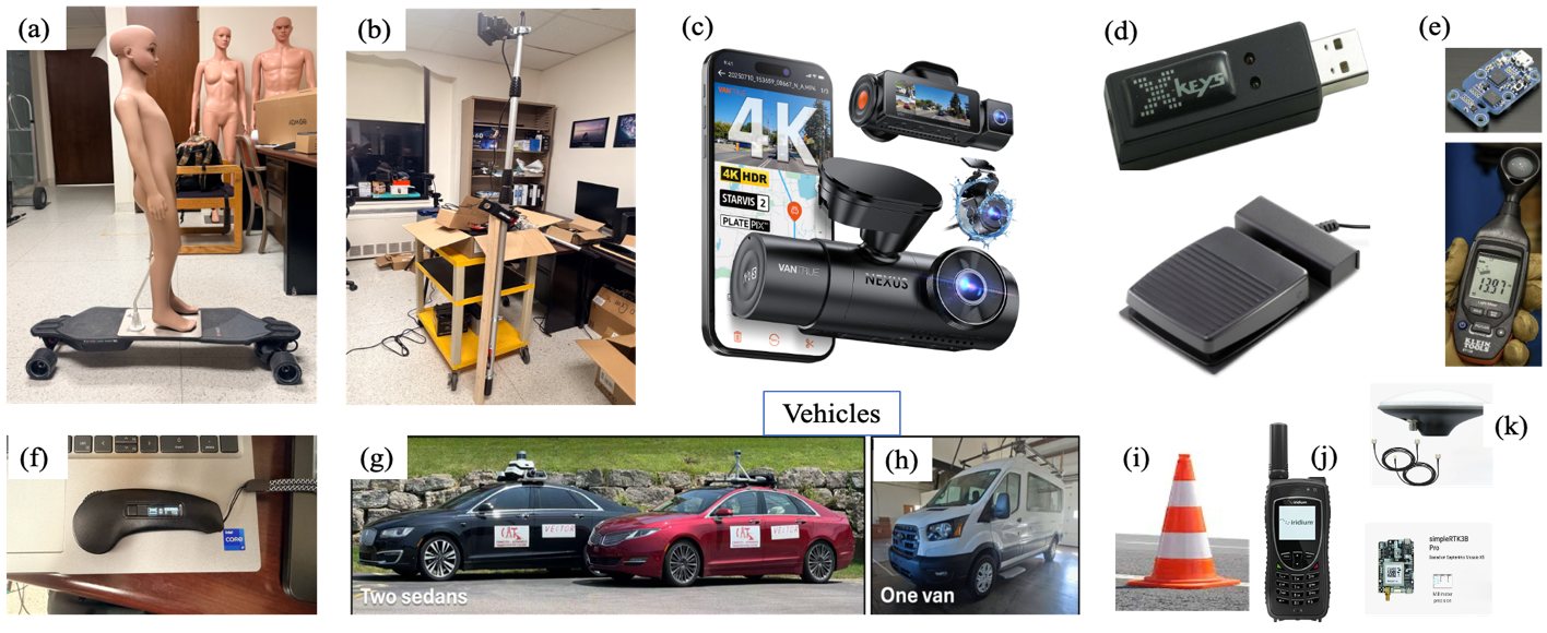
Drivers were never told when or where the mannequin would cross.
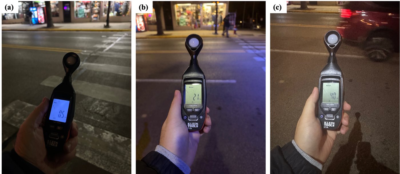
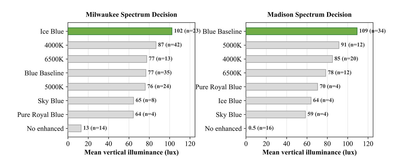
Measured illuminance at the crosswalk (Madison)
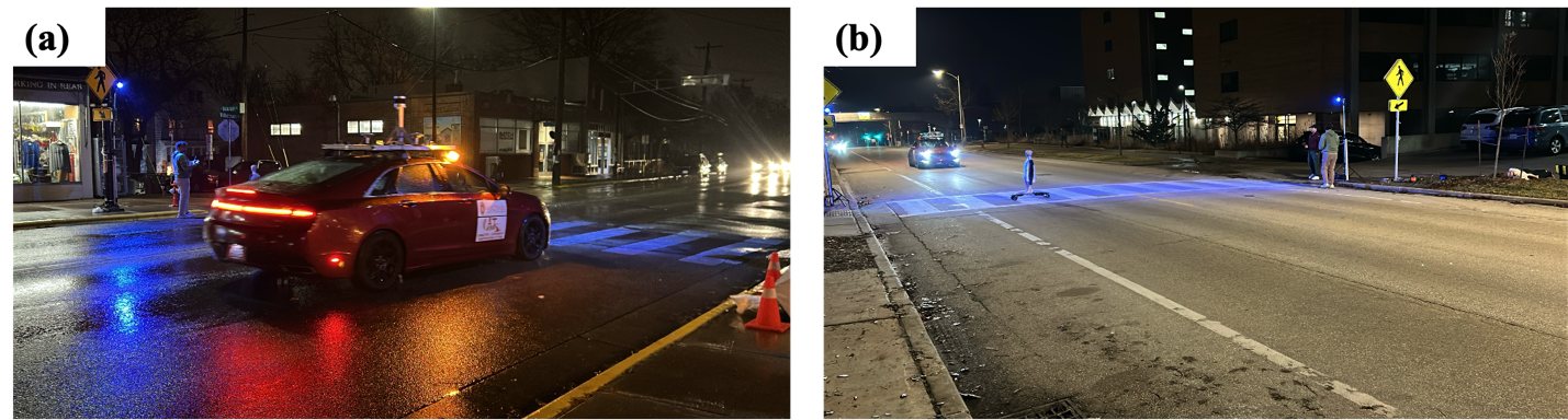
Field effort under harsh and tough conditions
All 281 rounds ran at night, including light rain, wet pavement, and late-season cold.
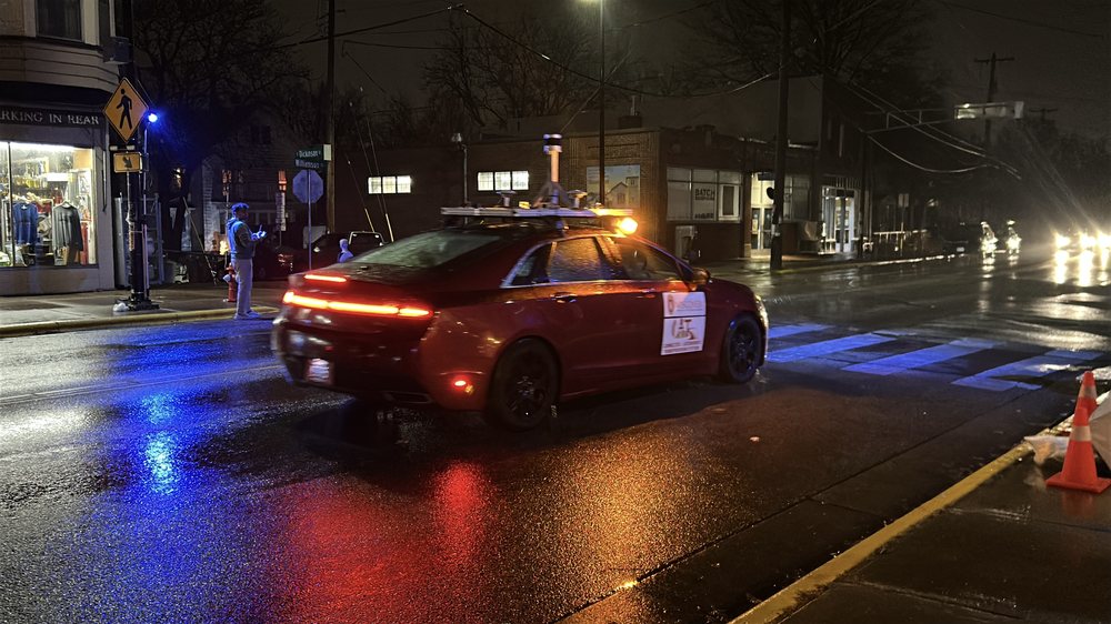
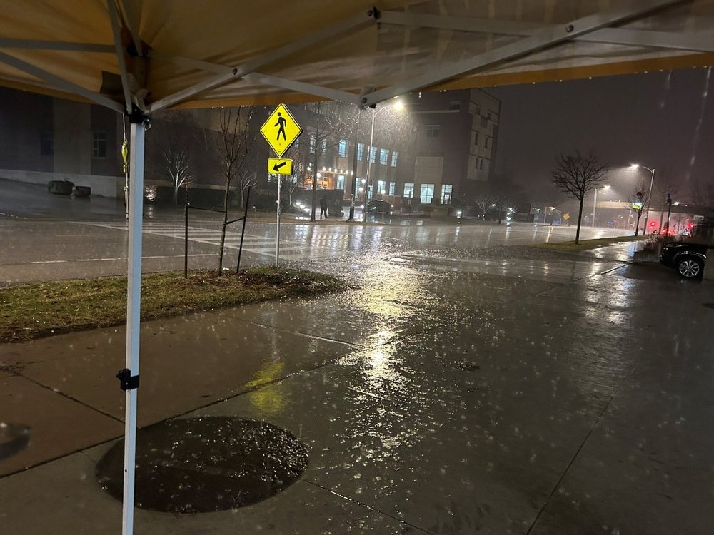
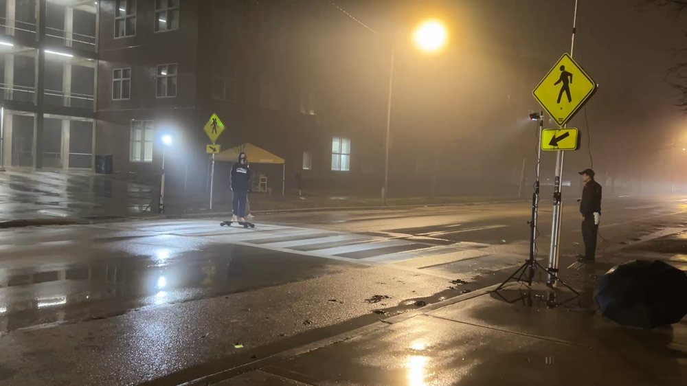
Field measurements, eye tracking, and driver-response analysis
A CNN pipeline found the exact frame each driver first recognized the pedestrian, then synchronized it with GPS, speed, and brake records.
Experimental design and synchronized measurements
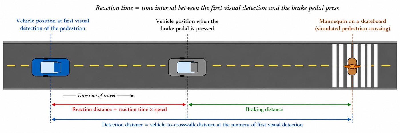
Controlled mannequin crossings and vehicle approaches compare lighting spectra, installation geometry, and pedestrian and roadway conditions. Roadway video, driver-facing infrared video (30 fps), 125 Hz GPS, brake records, and illuminance measurements capture each encounter. Time alignment connects eye onset with the vehicle trajectory and brake event.
Eye tracking and recognition onset
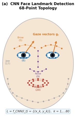
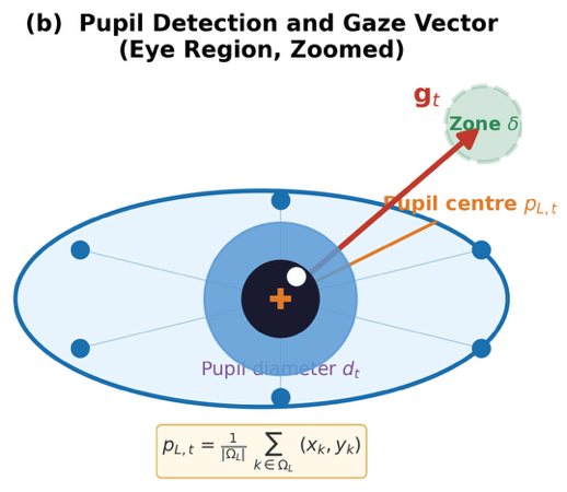
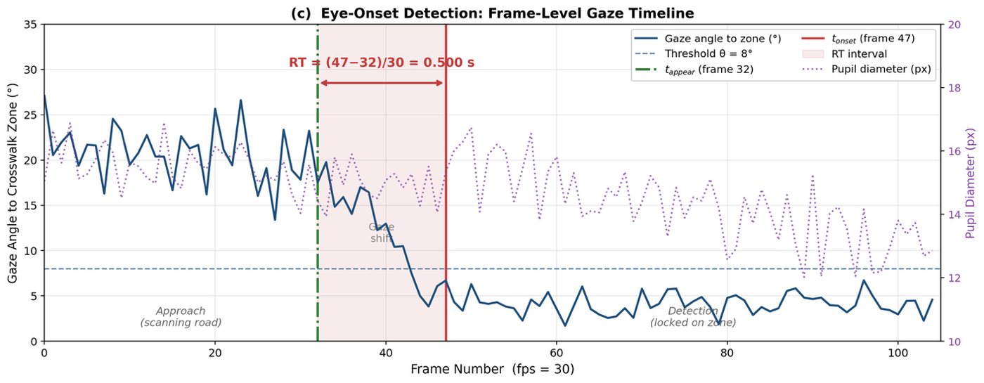
- Reaction time (RT)
- Time from first recognition to brake press; shorter indicates faster response.
- Detection distance (DD)
- Vehicle-to-crosswalk distance at first recognition; longer indicates earlier detection.
Quality control
Every eye onset was verified against the driver video, the roadway video, and the brake-event timestamp before analysis.
Face detection 95.6% combined 93.8% Milwaukee 98.6% Madison 30 fps IR video · ≈33 ms resolution Blinks, saccades & head pose filtered from noiseOnly trials passing synchronization, video, GPS, and brake-match checks entered the final analysis.
Field demonstrations and eye-tracking analysis
N Maryland Ave · two-lane campus roadway
Williamson St & S Dickinson St · RRFB site
Driver-facing infrared video · onset detection
Earlier detection under enhanced illumination
Madison · Blue Baseline
Milwaukee · Ice Blue
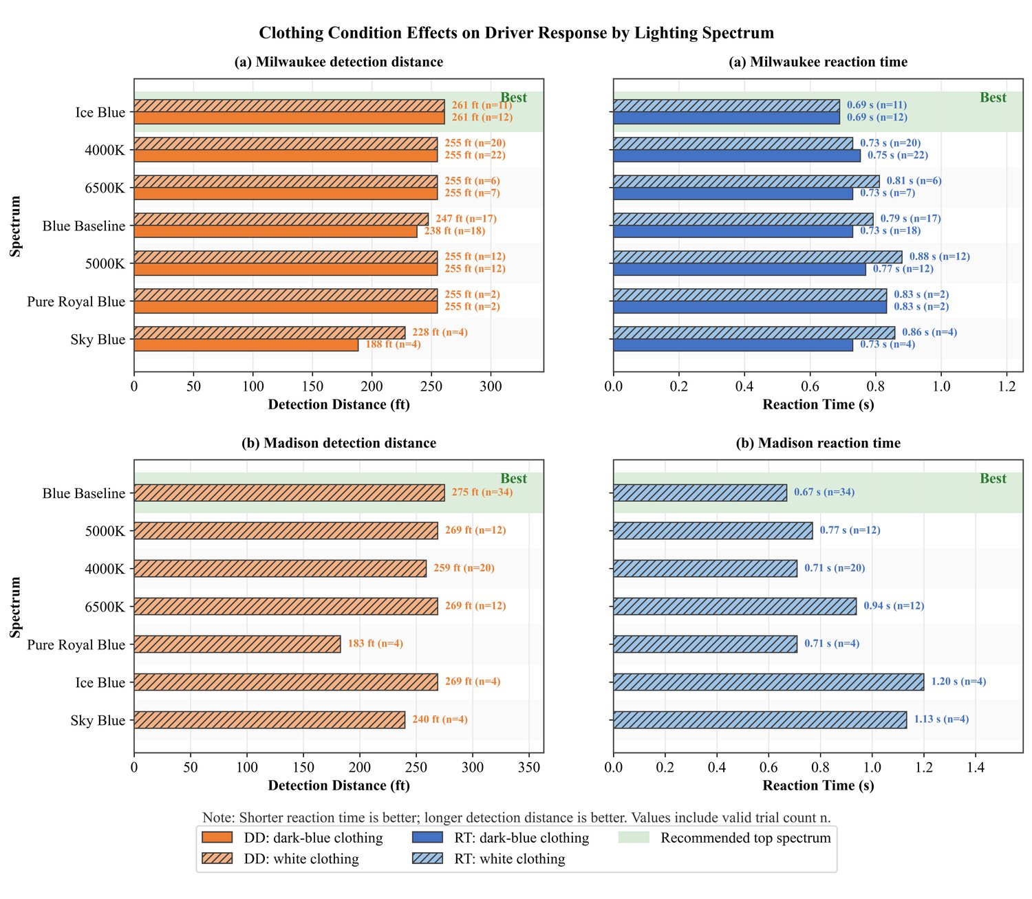
In these field experiments, the selected enhanced configurations increased detection distance and reduced reaction time relative to each site’s baseline. The preferred spectrum differed by site: Blue Baseline in Madison and Ice Blue in Milwaukee.
These comparisons describe the tested configurations at two sites. Transfer to other roadways requires review of geometry, illumination coverage, and glare.
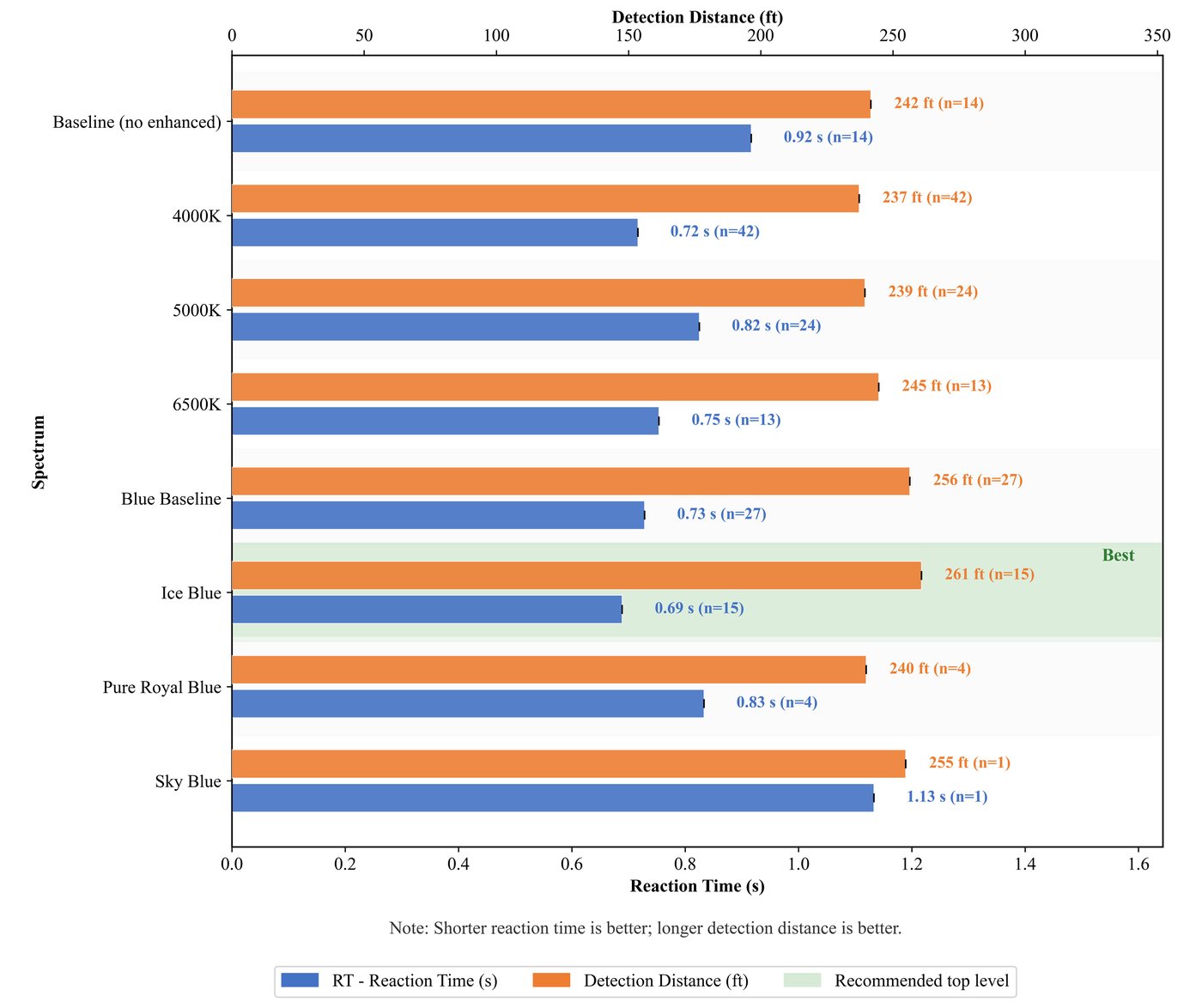
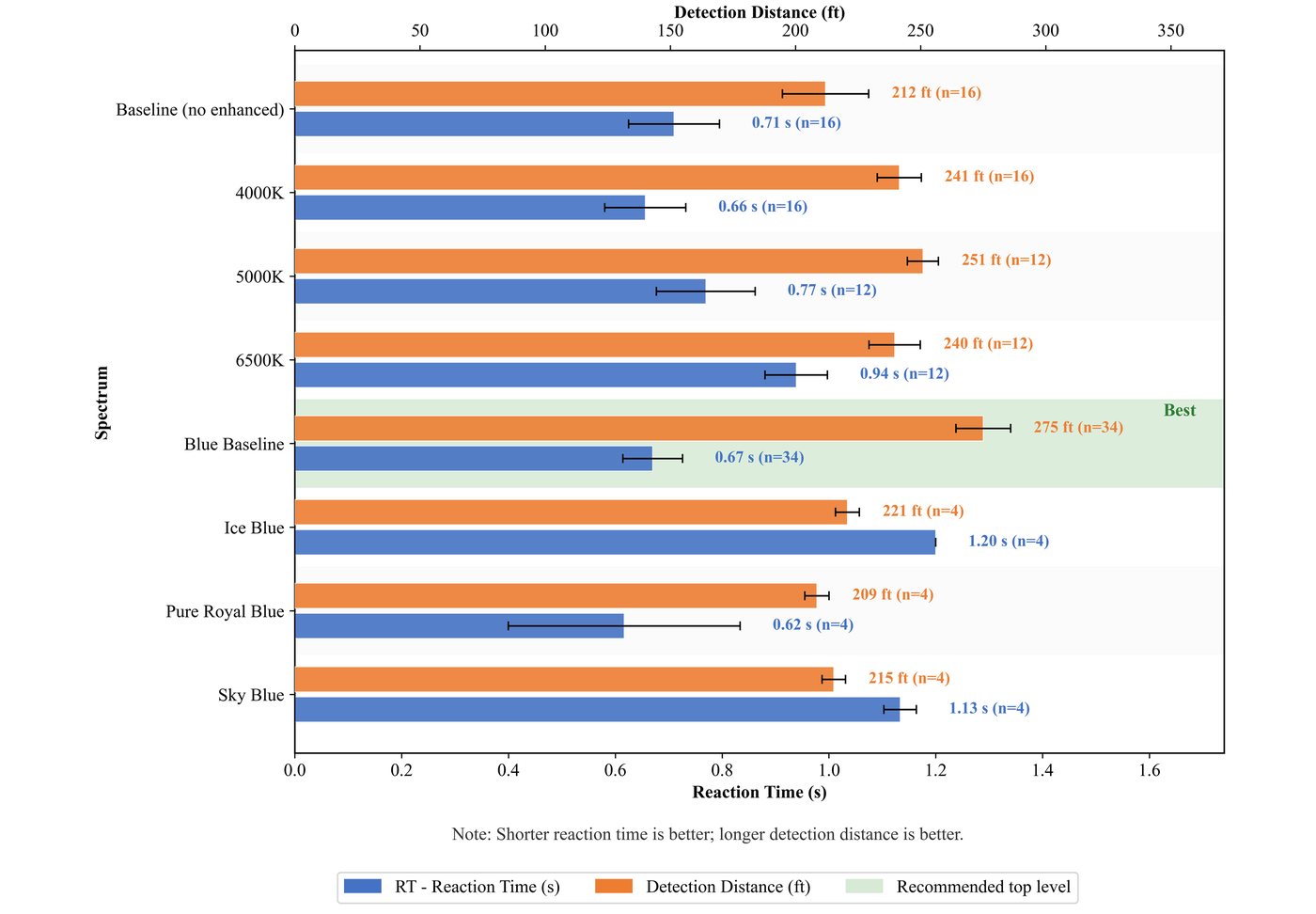
Lighting spectrum
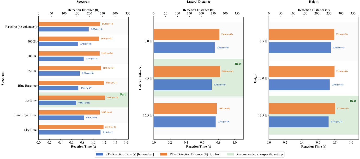
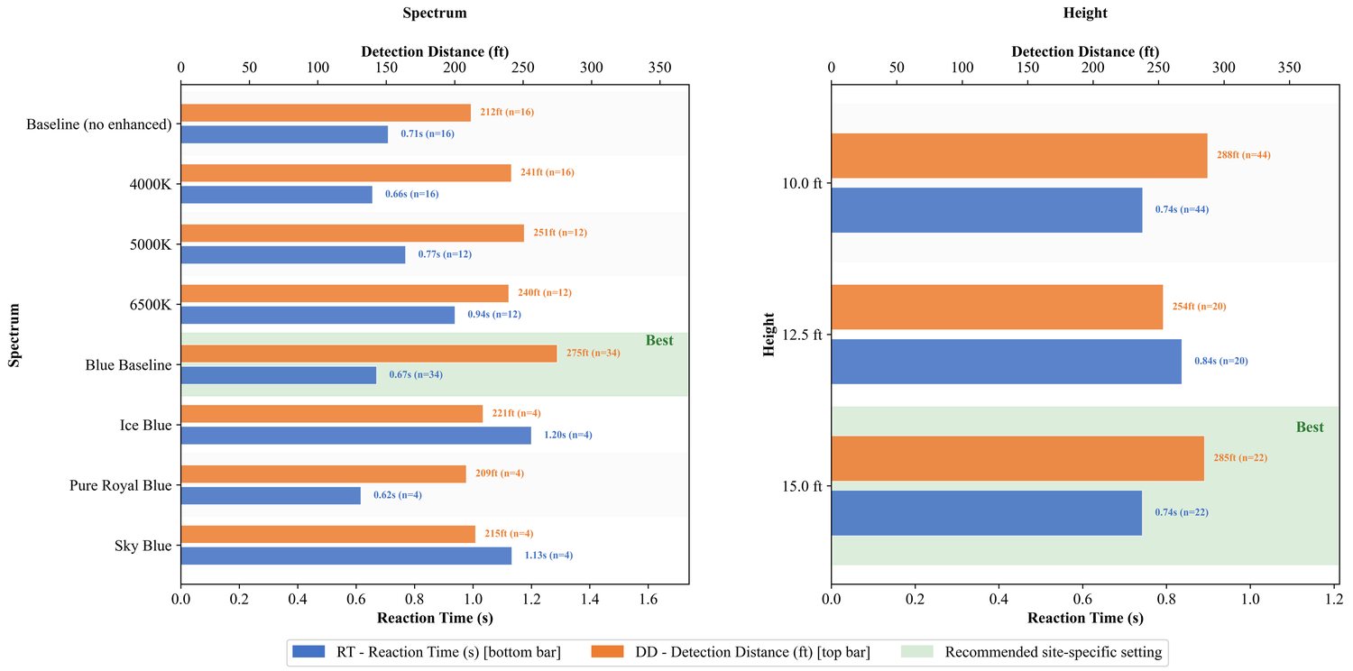
Source-reported reaction time (RT, seconds) and detection distance (DD, feet) for every tested spectrum.
Milwaukee · 177 nighttime rounds
| Spectrum | RT (s) | DD (ft) |
|---|---|---|
| Baseline (no enhanced) | 0.92 | 242.0 |
| 4000 K | 0.72 | 237.2 |
| 5000 K | 0.82 | 239.4 |
| 6500 K | 0.75 | 244.6 |
| Blue Baseline | 0.73 | 256.4 |
| Ice Blue ★ | 0.69 | 260.8 |
| Pure Royal Blue | 0.83 | 239.9 |
| Sky Blue | 1.13 | 254.8 |
Ice Blue: RT 0.69 s and DD 260.8 ft. Blue Baseline exceeded 4000 K by 19.2 ft in detection distance.
Madison · 104 nighttime rounds
| Spectrum | RT (s) | DD (ft) |
|---|---|---|
| Baseline (no enhanced) | 0.71 | 212.0 |
| 4000 K | 0.66 | 241.8 |
| 5000 K | 0.77 | 251.3 |
| 6500 K | 0.94 | 240.0 |
| Blue Baseline ★ | 0.67 | 275.0 |
| Ice Blue | 1.20 | 221.3 |
| Pure Royal Blue | 0.62 | 209.1 |
| Sky Blue | 1.13 | 215.9 |
Blue Baseline: RT 0.67 s and DD 275.0 ft, 33.2 ft beyond 4000 K and 63 ft beyond baseline.
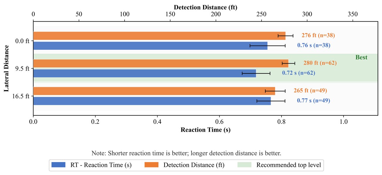
Installation geometry and combined configurations
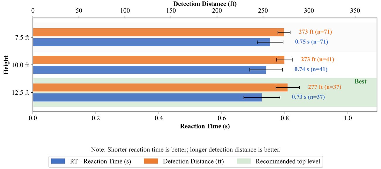
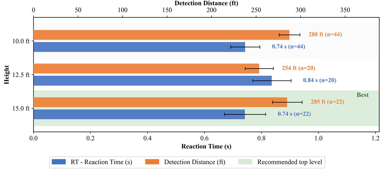
Source-selected configurations: Milwaukee—Ice Blue, 12.5 ft mounting height, 9.5 ft lateral placement; Madison—Blue Baseline, 15.0 ft mounting height. Lateral placement was not independently varied in Madison. Both source recommendations specify no spill control.
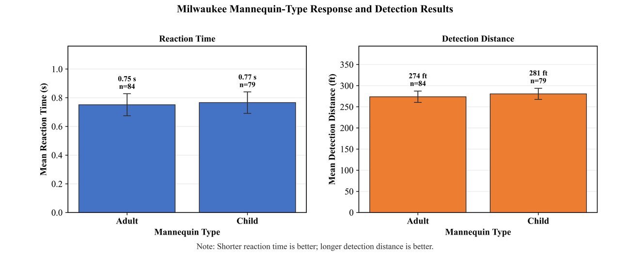
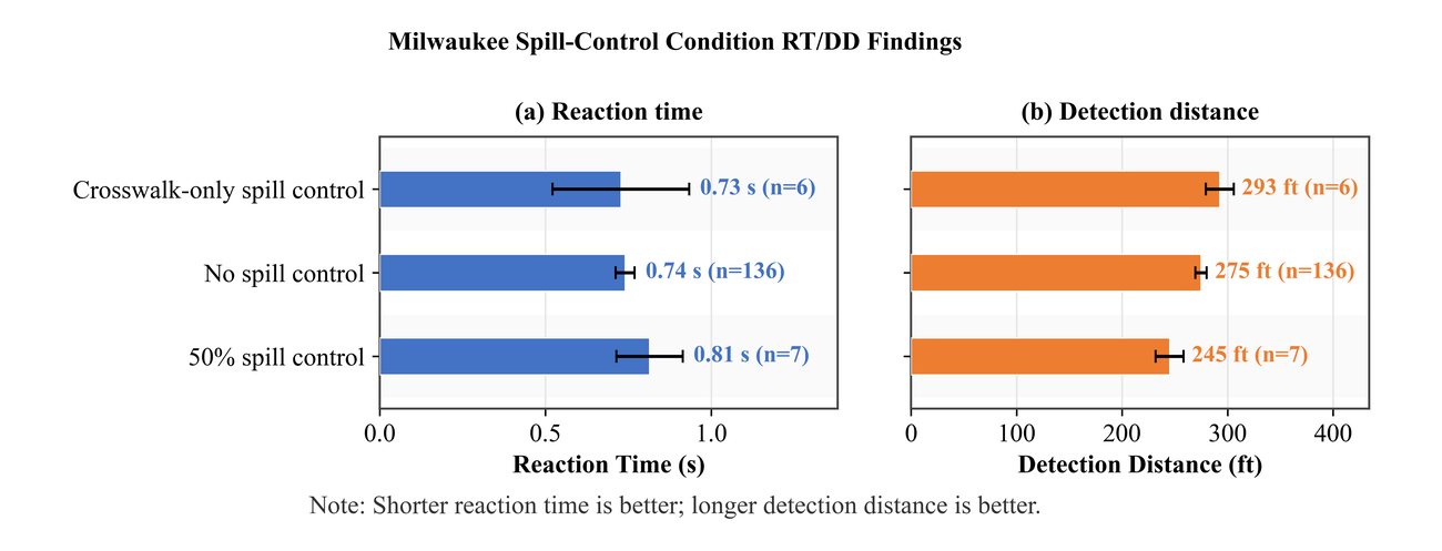
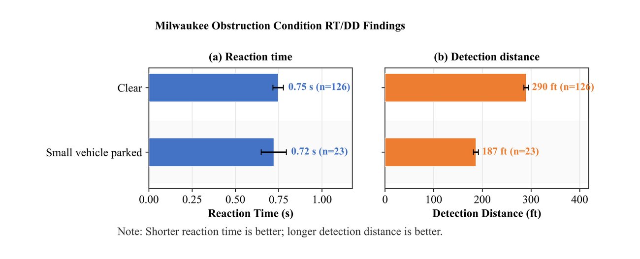
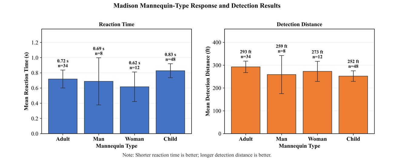
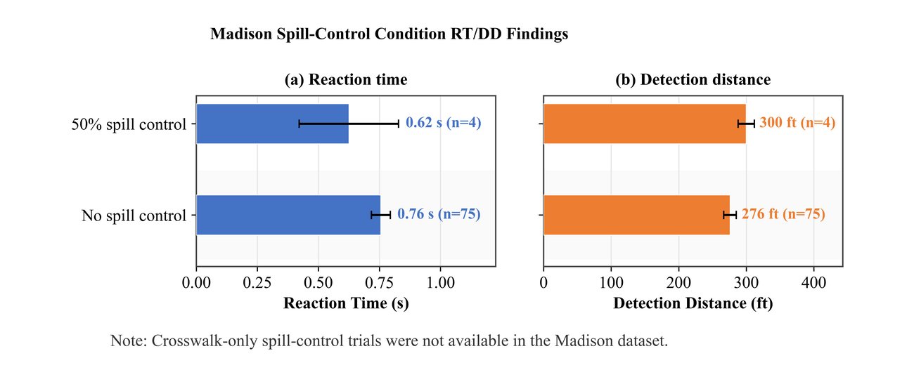
Pedestrian characteristics, spill control, and obstructions
Cross-site comparison
Preferred spectra differed by roadway context: Ice Blue in Milwaukee and Blue Baseline in Madison. The source carries Blue Baseline forward for generalized guidance; roadway geometry, coverage, and glare still require site review.
Eye-tracking and visual-response metrics · N = 163
| Metric | Baseline | Enhanced | p | Meaning |
|---|---|---|---|---|
| Pupil diameter | 5.31 mm | 4.87 mm | <0.001 | Pupil constriction under enhanced light |
| Contrast ratio | 0.72 | 0.88 | <0.001 | Higher pedestrian–background contrast ✓ |
| Glare index | 0.18 | 0.31 | <0.001 | Increased: monitor glare in design ⚠ |
| Visual comfort score | 3.82 | 3.41 | 0.002 | Slight comfort reduction |
| Blink rate | 0.31 /s | 0.22 /s | <0.001 | Reduced blink rate |
| Pupil asymmetry | 0.08 | 0.13 | <0.001 | Greater asymmetry; possible glare indicator ⚠ |
| Eye aspect ratio | 0.284 | 0.298 | 0.041 | Slightly higher under enhanced lighting |
| Saccade velocity | 142.3°/s | 168.7°/s | <0.001 | Faster visual scanning ✓ |
Enhanced lighting increased contrast and saccade velocity, alongside higher glare index and slightly lower visual comfort. These results support site-specific glare review.
Source-recommended lighting specifications
| Application context | Spectrum | Height | Lateral | Power |
|---|---|---|---|---|
| 2-lane residential (Milwaukee-type) | Ice Blue | 12.5 ft | 9.5 ft | Solar + battery |
| Wider urban (Madison-type) | Blue Baseline | 15.0 ft | Site-specific | Solar + battery |
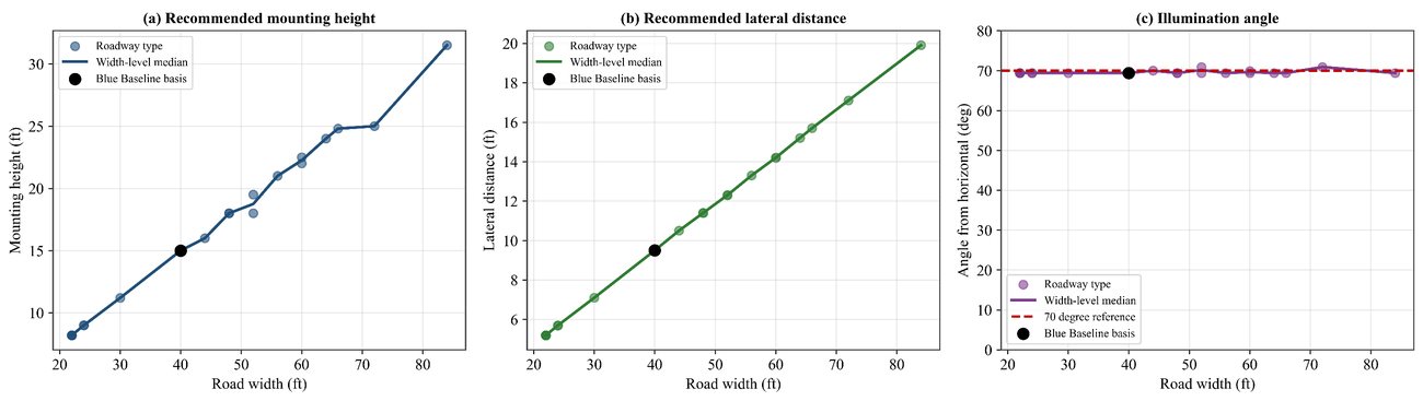
| Generalized guidance | Blue Baseline | Width-scaled | Width-scaled | Solar + battery |
Design illuminance ≥ 20 lux vertical at the pedestrian plane (≈ 21 lux measured in the field). Source recommendations specify no spill control, with site-specific glare review. Generalized specifications are planning guidance and require engineering verification.
From two sites to any Wisconsin crosswalk
A planning-level framework, not a fixed standard. Every site still gets engineering review and nighttime verification.
Blue Baseline OLS models
| Variable | RT | DD |
|---|---|---|
| Mounting height | 0.038 * | 1.452 |
| Lateral distance | −0.004 | −1.271 |
| Road width | −0.001 | 1.395 |
| Vehicle speed | 0.012 | 7.244 ** |
| Child vs. adult | 0.106 | −34.568 |
| High vs. medium ambient | 0.065 ** | 3.457 |
| R² | 0.208 | 0.451 |
* p < 0.1 · ** p < 0.05. The DD model (R² = 0.451) is the useful screen; predicted DD compares directly with SSD. Exploratory planning tool only.
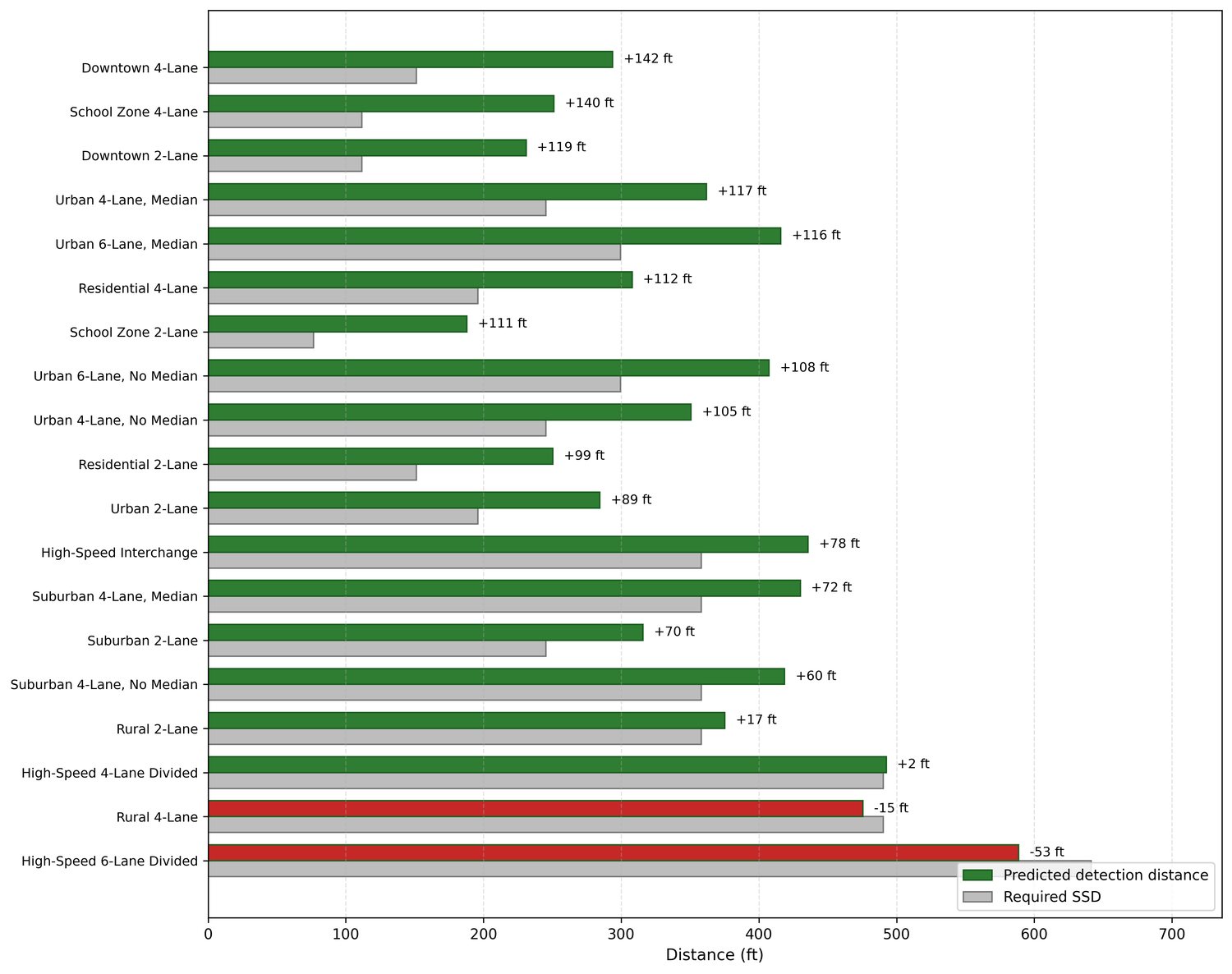
Stopping sight distance screen
Predicted detection distance must exceed AASHTO-required SSD (2.5 s perception-reaction, f = 0.35, level grade).
Pass School-zone, residential, downtown, urban, most suburban
Marginal High-speed 4-lane divided: verify before advancing
Fail Rural 4-lane · high-speed 6-lane divided: revise design first
Required checks before installation
Implementation recommendations
| Design element | Recommended direction |
|---|---|
| Primary spectrum | Blue Baseline (blue-shifted LED; controller RGB R 129.0 · G 420.75 · B 741 on the 0–750 scale) · Ice Blue (R 80 · G 520 · B 750) for narrow two-lane residential contexts |
| Vertical illuminance | ≥ 20 lux at the pedestrian plane (≈ 21 lux measured in the field) |
| Mounting height | Scale with roadway width (10.6 ft @ 22 ft road → 19.2 ft @ 72 ft road) · verify photometrically |
| Lateral placement | Scale with roadway width (5.6–13.7 ft) · adjust for poles, glare, coverage |
| Power source | Solar + battery storage, subject to site feasibility |
| Safety screening | Predicted detection distance must exceed required SSD for the approach speed |
Blue-spectrum lighting reduced RT and increased DD vs. baseline at both sites.
It must combine with illuminance, contrast, coverage, glare control, and geometry.
Ice Blue for two-lane; Blue Baseline for wider roads and generalized use.
Scale height and placement with roadway width; never copy between sites.
Predicted DD must exceed required SSD, or the site needs additional review.
Pilot deployments · larger datasets · adaptive dimming · winter validation · glare monitoring · statewide guidance updates.
Questions, corrections, and suggestions
Reviewing this study? Send a comment to the research team at UW–Milwaukee. Technical questions, data requests, implementation suggestions, and corrections are all welcome.